Technical Specifications
| Product | Pneumatic Valves |
| Category | Industrial Valves & Automation Solutions |
| Typical Applications | Factory automation, Packaging machines, Pneumatic actuators, Process control |
| Size / pressure class / end connection | Available as per customer requirement – mention in enquiry |
| Body material and media handled | Available as per customer requirement – mention in enquiry |
| Operation (manual / gear / pneumatic / electric) | Available as per customer requirement – mention in enquiry |
| Quantity and delivery location | Available as per customer requirement – mention in enquiry |
| Brands / Makes | Available from our represented brands in this division: Zoloto Valves, Duncan Engineering Limited, Marck Industrial Valves, V-Tork, Lehry Valves, Rumax, Pennant |
Product Information
Pneumatic Valves — Technical Overview & Selection Guide
Overview
Pneumatic valves are mechanical or pneumatically actuated valves designed to control the direction, pressure, flow, and isolation of compressed air and other compatible gases in industrial systems. They operate through pneumatic signals, compressed air pressure, or pneumatic actuators to open, close, or regulate the flow path according to the application requirements.
Pneumatic valves are widely used in industrial automation, manufacturing, process control, and fluid power systems. They are commonly integrated with PLC systems, pneumatic control panels, air preparation units, cylinders, actuators, automated machinery, and production equipment to provide reliable and repeatable control of pneumatic operations.
Key Features
-
Reliable control of compressed air and compatible gases
-
Suitable for directional, pressure, flow, and on/off control
-
Manual, mechanical, pneumatic, and solenoid-pilot actuation options available
-
Available in 2-way, 3-way, 4-way, and 5-way configurations, depending on design
-
Fast switching and repeatable operation
-
Compact and modular construction options
-
Suitable for single-acting and double-acting pneumatic cylinders
-
Available in normally open and normally closed configurations, where applicable
-
Spring-return and detented operating options available
-
Suitable for automated and high-cycle applications
-
Available in different port sizes, flow capacities, and pressure ratings
-
Threaded, manifold-mounted, sub-base, and push-in connection options available
-
Low-maintenance designs available, depending on operating conditions
-
Compatible with PLCs, sensors, solenoid coils, and pneumatic control systems
-
Suitable for industrial machinery and automated production lines
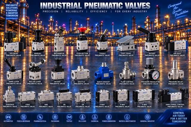
Common Pneumatic Valve Types
-
2/2-Way Pneumatic Valve
-
3/2-Way Pneumatic Valve
-
4/2-Way Pneumatic Valve
-
4/3-Way Pneumatic Valve
-
5/2-Way Pneumatic Valve
-
5/3-Way Pneumatic Valve
-
Directional Control Valve
-
Pneumatically Operated Directional Valve
-
Solenoid-Pilot Pneumatic Valve
-
Manual Pneumatic Valve
-
Mechanical Pneumatic Valve
-
Foot-Operated Pneumatic Valve
-
Push-Button Pneumatic Valve
-
Roller Lever Pneumatic Valve
-
Pneumatic Pressure Relief Valve
-
Pneumatic Pressure Regulator Valve
-
Pneumatic Flow Control Valve
-
One-Way Flow Control Valve
-
Quick Exhaust Valve
-
Check Valve / Non-Return Valve
-
Shuttle Valve
-
Dual-Pressure Valve
-
Pneumatic Sequence Valve
-
Pneumatic Logic Valve
-
Pneumatic Dump / Soft-Start Valve
-
Pneumatic Isolation Valve
-
Pneumatic Safety Valve, where applicable
Technical Selection Parameters
Selection should consider:
| Parameter | Selection Consideration |
|---|---|
| Valve Type | Directional / Pressure / Flow Control / Check / Quick Exhaust |
| Valve Configuration | 2/2 / 3/2 / 4/2 / 4/3 / 5/2 / 5/3, as applicable |
| Actuation Type | Manual / Mechanical / Pneumatic / Solenoid-Pilot |
| Return Mechanism | Spring Return / Air Return / Detented / Other |
| Valve Function | On/Off / Directional / Pressure Regulation / Flow Control |
| Port Size | DN / NPS / BSP / NPT / Metric, as applicable |
| Operating Pressure | Minimum / Normal / Maximum |
| Pressure Rating | As applicable to valve design |
| Control Pressure | Required pilot pressure, where applicable |
| Flow Capacity | Minimum / Normal / Maximum Flow or Rated Flow |
| Flow Coefficient | Cv / Kv / Manufacturer-Specified Flow Rating |
| Medium | Compressed Air / Compatible Gas |
| Air Quality | Filtration / Moisture / Oil Content Requirements |
| Operating Temperature | Minimum / Normal / Maximum |
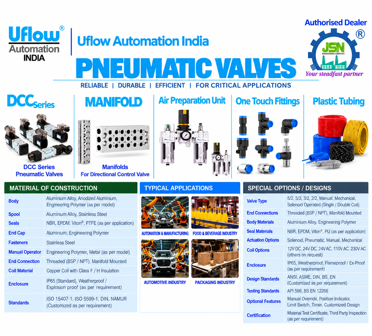
| Body Material | Aluminium / Brass / Stainless Steel / Engineered Polymer |
| Internal Material | Stainless Steel / Brass / Alloy / Other Suitable Materials |
| Seal Material | NBR / FKM / EPDM / Other Compatible Materials |
| Port Arrangement | Inline / Manifold / Sub-Base Mounted |
| End Connection | Threaded / Push-In / Tube / Manifold |
| Electrical Supply | AC / DC, for solenoid-pilot valves |
| Coil Voltage | As required by the control system |
| Electrical Connection | DIN Connector / Lead Wire / Terminal / Other |
| Enclosure Protection | Required IP Rating, where applicable |
| Installation | Inline / Panel / Manifold / Machine-Mounted |
| Response Time | Required Switching Response |
| Duty Cycle | Continuous / Intermittent / High-Cycle |
| Exhaust Arrangement | Open Exhaust / Exhaust Port / Silencer |
| Application | Cylinder Control / Air Distribution / Automation / Safety |
| Mounting Standard | Applicable Manufacturer or Industry Standard |
Materials
Common pneumatic valve body materials include:
-
Aluminium
-
Brass
-
Stainless Steel
-
Zinc Alloy, where applicable
-
Engineered Polymer
-
Carbon Steel, where applicable to the design
Internal components such as spools, poppets, plungers, springs, valve seats, guides, seals, and exhaust components should be selected according to operating pressure, temperature, air quality, corrosion resistance, switching frequency, mechanical wear, and required service life.
For applications involving corrosive environments or special gases, material compatibility should be confirmed with the valve manufacturer.
Seal & Seat Selection
Common sealing materials may include:
-
NBR
-
FKM
-
EPDM
-
Polyurethane (PU)
-
PTFE
-
Other specialty elastomers or polymers
Selection should consider compressed-air quality, operating pressure, temperature, chemical compatibility, lubrication requirements, wear resistance, leakage limits, and expected operating cycles.
The seal material must be compatible with the intended medium and operating environment. Not every sealing material is suitable for every pneumatic application.
Actuation & Control Selection
Pneumatic valves should be selected according to the required control method, operating sequence, and automation arrangement.
Selection may consider:
-
Manual Actuation
-
Mechanical Actuation
-
Pneumatic Pilot Actuation
-
Solenoid-Pilot Actuation
-
Single-Solenoid or Double-Solenoid Operation
-
Spring Return or Air Return
-
Detented or Non-Detented Operation
-
Single-Acting or Double-Acting Cylinder Control
-
PLC or Relay-Based Control
-
Pilot Pressure Requirements
-
Switching Frequency
-
Response Time
-
Fail Position and Return Behaviour
-
Manual Override, where applicable
-
Electrical Supply and Coil Power, for solenoid-pilot designs
-
Required Safety and Interlocking Functions
Common electrical supply options for solenoid-pilot pneumatic valves may include:
-
12 VDC
-
24 VDC
-
24 VAC
-
110 VAC
-
230 VAC
Actual voltage, coil power, connector type, and control configuration should be selected according to the control system and manufacturer’s available options. Purely pneumatic or manually operated valves do not require an electrical supply.
End Connections & Mounting
Pneumatic valves may be supplied with:
-
BSP Threaded Connections
-
NPT Threaded Connections
-
Metric Threaded Connections
-
Push-In Fittings
-
Tube Connections
-
Inline Port Connections
-
Manifold-Mounted Connections
-
Sub-Base-Mounted Connections
-
NAMUR Interface Mounting, where applicable
-
Other connections according to valve design
The connection and mounting arrangement should match the pneumatic piping, tubing size, operating pressure, available installation space, required flow capacity, and applicable project specifications.
For manifold-mounted valves, port arrangement, electrical connection, mounting interface, and compatibility with the selected manifold should be verified before ordering.
Operation
Pneumatic valves operate by shifting an internal spool, moving a poppet, or changing the position of another flow-control element. This action directs compressed air through designated ports to control pneumatic cylinders, actuators, and other equipment.
Depending on the valve design, actuation may be provided manually, mechanically, pneumatically, or through an electrically operated solenoid pilot.
Pneumatic valves may be configured as:
-
Normally Closed (NC): Blocks the specified flow path in its normal state, where applicable.
-
Normally Open (NO): Allows the specified flow path in its normal state, where applicable.
-
Spring Return: Returns the valve to its defined normal position when the actuating force is removed.
-
Detented: Retains its last commanded position until another operating force changes it.
-
Monostable: Has one stable normal position.
-
Bistable: Can retain either of two commanded positions, depending on design.
-
Centre Closed: Blocks the working ports in the centre position of an applicable 3-position directional valve.
-
Centre Exhaust: Connects the working ports to exhaust in the centre position, where designed.
-
Centre Pressure: Connects the pressure supply to the working ports in the centre position, where designed.
The actual port connections and normal positions depend on the valve’s configuration and manufacturer’s circuit symbol.
Quick Selection Guide
Medium: Identify whether the valve will handle compressed air or another compatible gas. Confirm air quality and any special media requirements.
Application: Define whether the valve is intended for cylinder actuation, air distribution, pressure regulation, flow control, exhaust, isolation, or pneumatic logic.
Valve Type: Select a directional control, pressure control, flow control, check, quick exhaust, or other suitable pneumatic valve.
Configuration: Specify the required 2/2, 3/2, 4/2, 4/3, 5/2, or 5/3-way arrangement, as applicable.
Actuation: Select manual, mechanical, pneumatic, or solenoid-pilot operation according to the control method.
Normal Position: Specify the required normal state or return position, where applicable.
Pressure: Provide minimum, normal, and maximum operating pressure, including pilot pressure requirements where applicable.
Flow Rate: Specify the required flow capacity and the expected air consumption of the connected equipment. Confirm the manufacturer’s rated flow or Cv/Kv data.
Port Size: Specify the required port size, thread standard, tubing size, and connection type.
Temperature: Provide minimum, normal, and maximum operating temperatures for the medium and surrounding environment.
Body Material: Select aluminium, brass, stainless steel, engineered polymer, or another suitable material according to the application.
Seal Material: Select NBR, FKM, EPDM, PU, PTFE, or another compatible material according to operating conditions.
Electrical Supply: For solenoid-pilot valves, specify AC/DC supply, coil voltage, power consumption, and electrical connector.
Mounting: Confirm inline, panel, manifold, sub-base, or applicable NAMUR mounting requirements.
Exhaust: Define exhaust port arrangement and whether silencers or exhaust flow-control accessories are required.
Response Time: Consider the required switching speed and the operating frequency of the machinery.
Duty Cycle: Specify continuous or intermittent operation and the expected number of switching cycles.
Air Preparation: Confirm filtration, pressure regulation, moisture removal, and lubrication requirements according to the valve manufacturer’s recommendations.
Fail Position: Identify the required safe state and return behaviour following loss of the pilot signal, electrical supply, or compressed-air supply. Verify the actual behaviour of the selected design.
Installation: Confirm installation orientation, ambient conditions, vibration exposure, and accessibility for maintenance.
Standards: Specify applicable industry standards, machine safety requirements, and project documentation requirements.
Testing & Inspection
Depending on project specifications, valve design, and applicable standards, pneumatic valves may undergo:
-
Body Pressure Testing
-
External Leakage Testing
-
Internal Leakage Testing
-
Functional and Operational Testing
-
Switching and Response-Time Verification
-
Flow Capacity Verification, where specified
-
Operating Pressure Verification
-
Pilot Pressure Verification
-
Spool or Poppet Movement Inspection
-
Spring Return and Detent Function Testing
-
Coil Electrical Testing, for solenoid-pilot valves
-
Insulation Resistance Testing, where applicable
-
Dielectric Strength Testing, where applicable
-
Dimensional Inspection
-
Port and Connection Inspection
-
Seal and Material Inspection
-
Visual and Surface Inspection
-
Mounting Interface Verification
-
IP/Enclosure Verification, where applicable
-
Certificate and Material Documentation Review, where specified
Testing requirements should be established according to the manufacturer’s procedures, applicable standards, purchase specifications, and the criticality of the application.
Applications
Pneumatic valves are commonly used in:
-
Oil & Gas Facilities
-
Refineries
-
Petrochemical Plants
-
Chemical Plants
-
Power Plants
-
Water and Wastewater Treatment
-
Manufacturing Industries
-
Automotive Assembly Lines
-
Packaging Machinery
-
Food and Beverage Processing, with suitable valve designs
-
Pharmaceutical Manufacturing, with suitable valve designs
-
Compressed Air Systems
-
Pneumatic Cylinder Control
-
Pneumatic Actuator Control
-
Process Automation
-
Instrumentation Systems
-
Material Handling Equipment
-
Conveyor Systems
-
Industrial Robotics
-
Machine Tools
-
Textile Machinery
-
Printing Machinery
-
HVAC and Utility Systems, where applicable
-
Industrial Equipment and Production Lines
-
Safety and Emergency Air-Dump Systems, where suitably designed and certified
Engineering Inputs for RFQ
For technical enquiry and quotation, provide:
Valve Type • Configuration • Normal Position • Size/Orifice • Pressure Rating • Minimum/Normal/Maximum Operating Pressure • Differential Pressure • Fluid • Flow Rate • Design Pressure • Operating & Design Temperature • Body Material • Internal Material • Seal & Seat Material • Coil Voltage • AC/DC Supply • Coil Power • Electrical Connection • IP/Enclosure Rating • Hazardous Area Classification, if applicable • End Connection • Installation Orientation • Response Time • Duty Cycle • Testing & Inspection Requirements
Manufacturer Brands
1. ZOLOTO — Industrial Valves
Brand: ZOLOTO
Website: www.zolotovalves.com
2. MARCK — Industrial Valves
Brand: MARCK
Manufacturer: Hawa Engineers Ltd.
Website: www.marckvalves.com
3. LEHRY — Industrial Valves and Instrumentation
Brand: LEHRY
Manufacturer: Lehry Instrumentation & Valves Pvt. Ltd.
Website: www.lehryvalves.com
4. UFLOW — Automation and Process Control Valves
Brand: UFLOW
Manufacturer: Uflow Automation India
Website: www.uflowvalve.com
5. V-TORK CONTROLS — Industrial Flow Control Valves
Brand: V-TORK CONTROLS
Website: www.vtorkcontrols.com
6. PENNANT — Steam Traps and Pipeline Accessories
Brand: PENNANT
Manufacturer: Pennant Engineering Pvt. Ltd.
Website: www.pennantcorp.com